Fusing Phase Map Servoing and MPC for High-Precision Robotic Tracking of Dynamic Objects
In one sentenceA robot tracks a moving object using its structured-light phase map directly as feedback. Thinning and compressing that map lets predictive control run in real time, tracking a 0.1 m/s target to 0.05 mm.
The problem
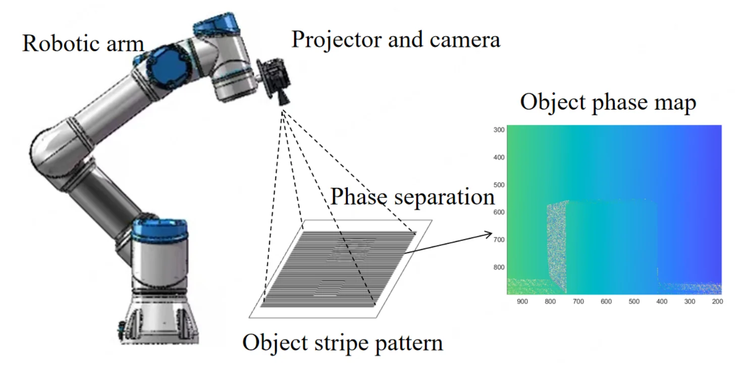
Industrial robots often work stop-and-go: move to a fixed pose, take an image, then act. To work on parts that keep moving on a conveyor, the robot must instead close the loop on continuous visual feedback, which is visual servoing. Conventional visual features such as points, edges and contours struggle on the textureless or specular surfaces common in industry. Phase maps from fringe projection are an alternative: a projector casts sinusoidal fringes, and the recovered phase gives dense, subpixel geometric information without a 3D reconstruction step. Earlier phase-map servoing work, however, dealt with static or slowly varying scenes.
A moving target adds two difficulties. Sensing and image processing delays make the measured phase map lag behind the object’s actual state, and the lag grows with target speed. Model predictive control (MPC) is well suited to dynamic tracking because it plans over future states under constraints, but applied directly to the thousands of phase pixels in a map it becomes too expensive to solve at a high rate.
How it works
The framework keeps the dense phase map as the feedback signal but shrinks the control problem built from it, so that MPC can run at the camera rate, and adds an Extended Kalman Filter (EKF) to look ahead past the sensing delay.
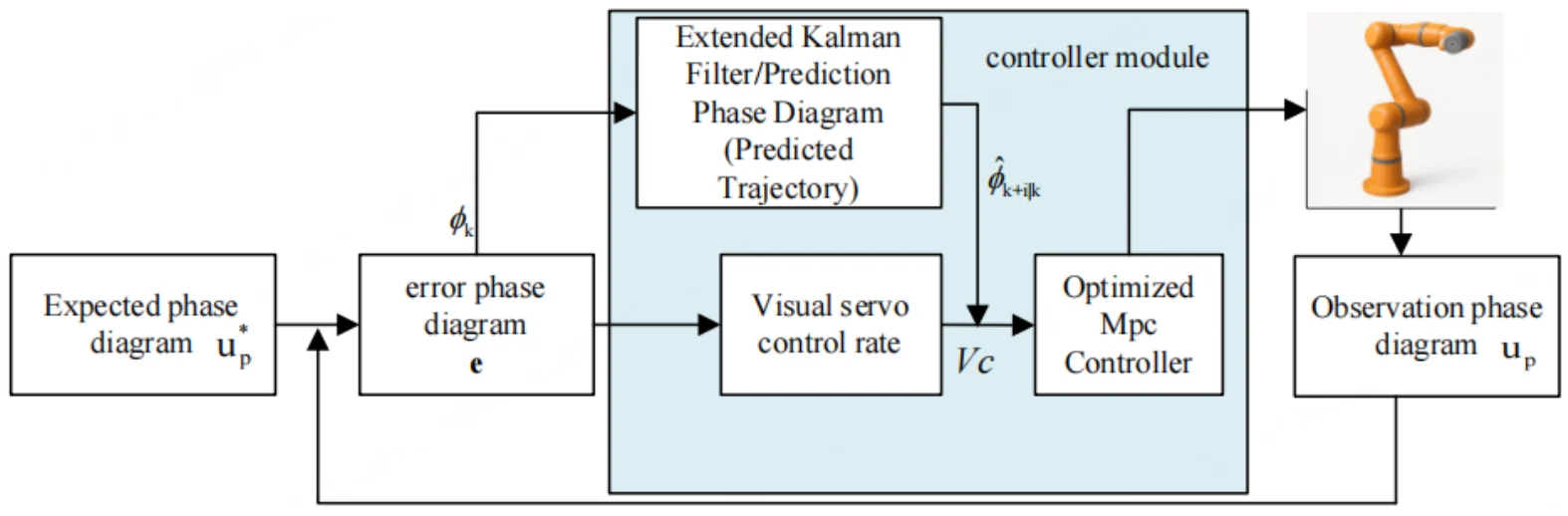
- Phase map as the feature. The camera and projector are mounted on the robot’s end effector. The difference between the observed and the desired phase map is mapped to a 6-DoF end-effector velocity through an analytically derived phase interaction matrix L, one row per phase pixel.
- Gradient-guided sparsification. Pixels whose phase gradient falls below a threshold ε carry little information about motion, so their rows of L are removed. In all experiments ε is 0.15 times the largest gradient magnitude.
- PCA embedding. The remaining phase features are projected onto d = 8 principal components, so MPC works with an 8 × 6 interaction matrix instead of an m × 6 one (m is the number of pixels in the phase map). In scenes with enough phase gradient, the reduced matrix keeps rank 6 and all six motion directions stay controllable.
- Adaptive prediction horizon. The MPC horizon follows the phase change rate: it stays at Nmin = 3 when the phase changes slowly and grows smoothly, through a tanh function, towards Nmax = 10 as the target speeds up.
- EKF prediction as the MPC reference. An EKF estimates the target’s position and velocity, propagates them over the horizon and converts each predicted position into a predicted phase map. MPC tracks this sequence as its reference, compensating for latency, and applies only the first control input of each solution.
Results
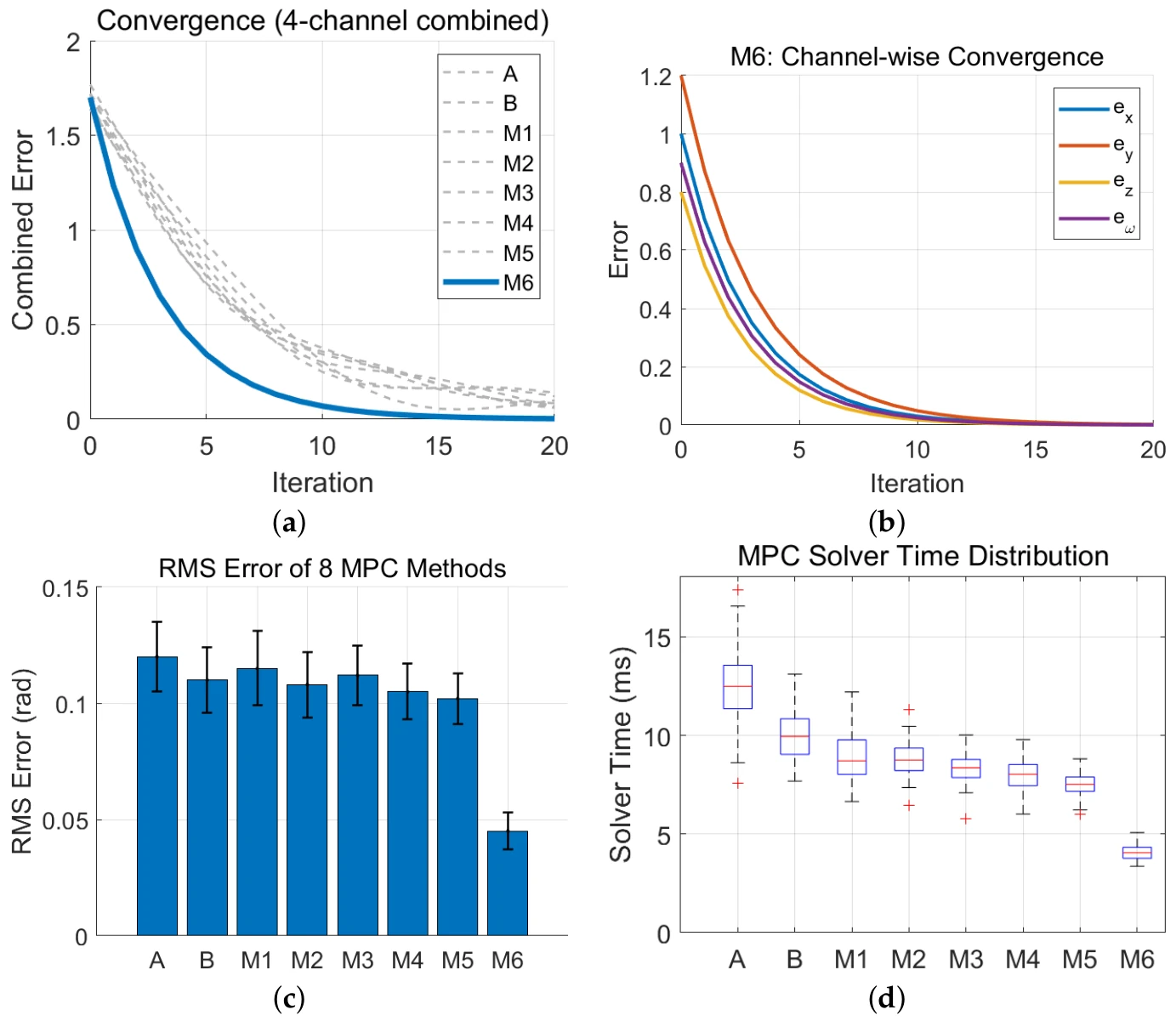
The simulation, run in MATLAB, compares eight controllers: two baselines (A, which uses the full phase map and recomputes the interaction matrix at every step, and B, which adds warm start to A) and six variants that use one, two or all three of the reductions (M1–M6). M6, which combines PCA, the sparse interaction matrix and the adaptive horizon, converges within about 20 iterations and has the lowest RMS error and the lowest, most compact solve-time distribution. A sweep of the reduction settings supports ε = 0.15 and d = 8 as the balance point: they give a 1.9 ms solve time and 0.048 mm RMS error (Table 2), against 3.5 ms and 0.042 mm for a looser setting (ε = 0.05, d = 12) and 1.3 ms with 0.081 mm for a more aggressive one (ε = 0.30, d = 6) (Table 2). Camera exposure, phase computation and the EKF update cost the same with or without the reductions; the time saved comes from the MPC/QP step. The tests used a 640 × 480 camera at 120 Hz and a single CPU thread on an Intel Core i7-12700, with the qpOASES solver.
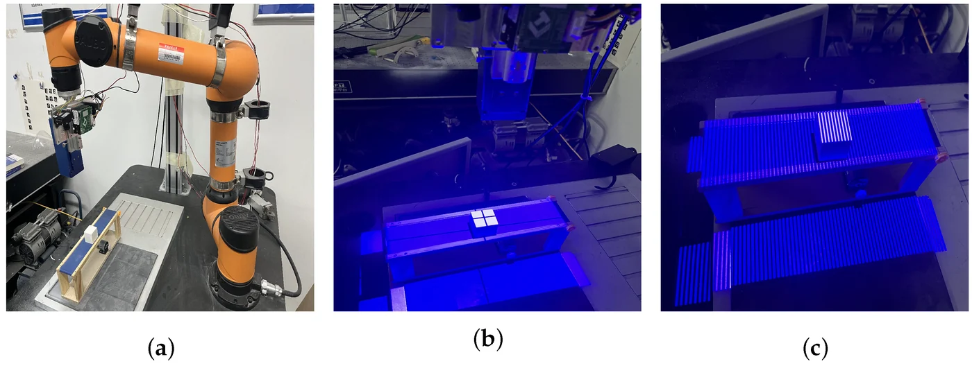
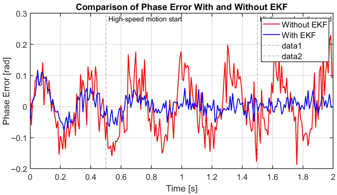
In the physical experiments, the projector–camera head rode on the robot arm and the object travelled on a conveyor. With a stationary object, the proposed controller reached the same accuracy as the original phase-map servo law, with errors around 0.3 mm, but converged in about 20 iterations instead of 30. The EKF matters most once the target moves fast: without it the phase error shows peaks approaching 0.2 rad, with it typical peaks stay below 0.1 rad.
The authors state that the reachable speed is limited by sensing throughput. With the 120 Hz camera and a control period of about 8.3 ms, tracking is stable up to about 0.12 m/s; above that, phase noise rises as phase-map generation cannot keep up, so results for faster targets are not reported. The current implementation tracks a single target under relatively controlled visual conditions; faster phase-map generation and multi-object tracking are left to future work.
Cite
@article{zhang2026fusing,
  title={Fusing Phase Map Servoing and MPC for High-Precision Robotic Tracking of Dynamic Objects},
  author={Zhang, Qinghui and Han, Tianhao and Lu, Lei and Pan, Wei and Gao, Ge},
  journal={Actuators},
  volume={15},
  number={2},
  pages={77},
  year={2026},
  publisher={MDPI},
  doi={10.3390/act15020077}
}