Generative deep-learning-embedded asynchronous structured light for three-dimensional imaging
Synchronising a structured light projector with a high-speed camera is a persistent engineering bottleneck: tight timing requirements impose hardware cost and limit frame rates. Asynchronous structured light removes this constraint by decoupling projector and camera clocks, but temporal misalignment between captured frames corrupts standard phase recovery algorithms. This paper introduces a generative deep learning model that learns to reconstruct coherent phase maps directly from asynchronously captured fringe images. Rather than correcting misalignment as a pre-processing step, the network jointly models the fringe formation process and the uncertainty introduced by timing jitter, producing probabilistically calibrated phase estimates. The framework is validated on a range of moving objects under varied lighting conditions. Published in Advanced Photonics (2024), one of the highest-impact optics journals, the work demonstrates measurement accuracy on par with synchronised systems at two to three times the imaging speed. This result is significant for industrial metrology, autonomous driving, and biomedical imaging where both speed and simplicity are critical.
Problem setting
Asynchronous structured light captures fringe patterns without strict hardware synchronisation between projector and camera, enabling higher frame rates and simpler system design, but introduces temporal misalignment that corrupts phase recovery. This work embeds a generative deep learning model—trained to hallucinate the missing or misaligned fringe phases—directly into the asynchronous structured light pipeline. The generative network learns a conditional distribution over phase maps given the observed asynchronous fringe images, allowing accurate phase recovery from fewer, temporally inconsistent captures.
The figures below collect representative visual evidence from Advanced Photonics, 6(4):046004.
Method and visual evidence
The figures below summarize the paper’s setup, signal flow, and visual evidence.
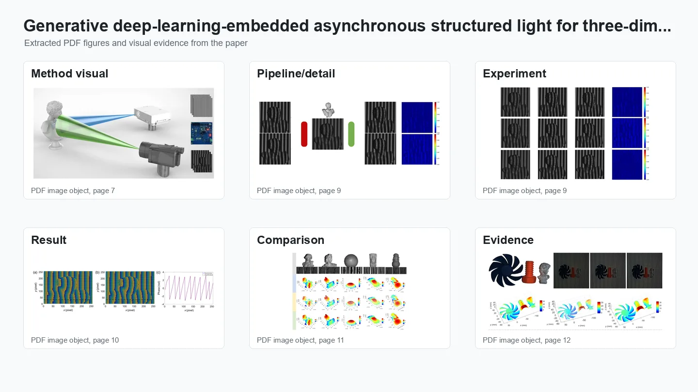
Method overview.
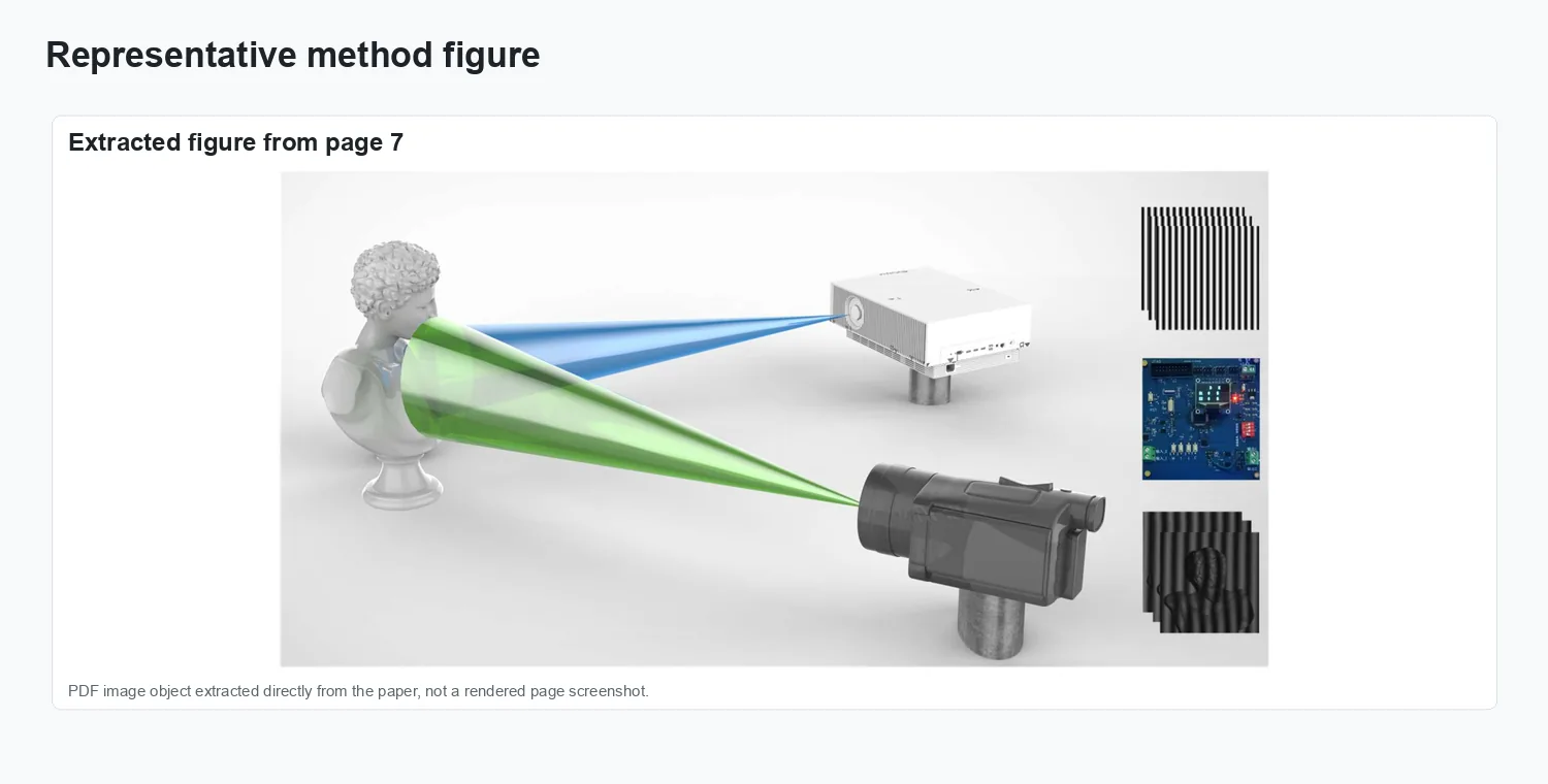
Representation and setup.
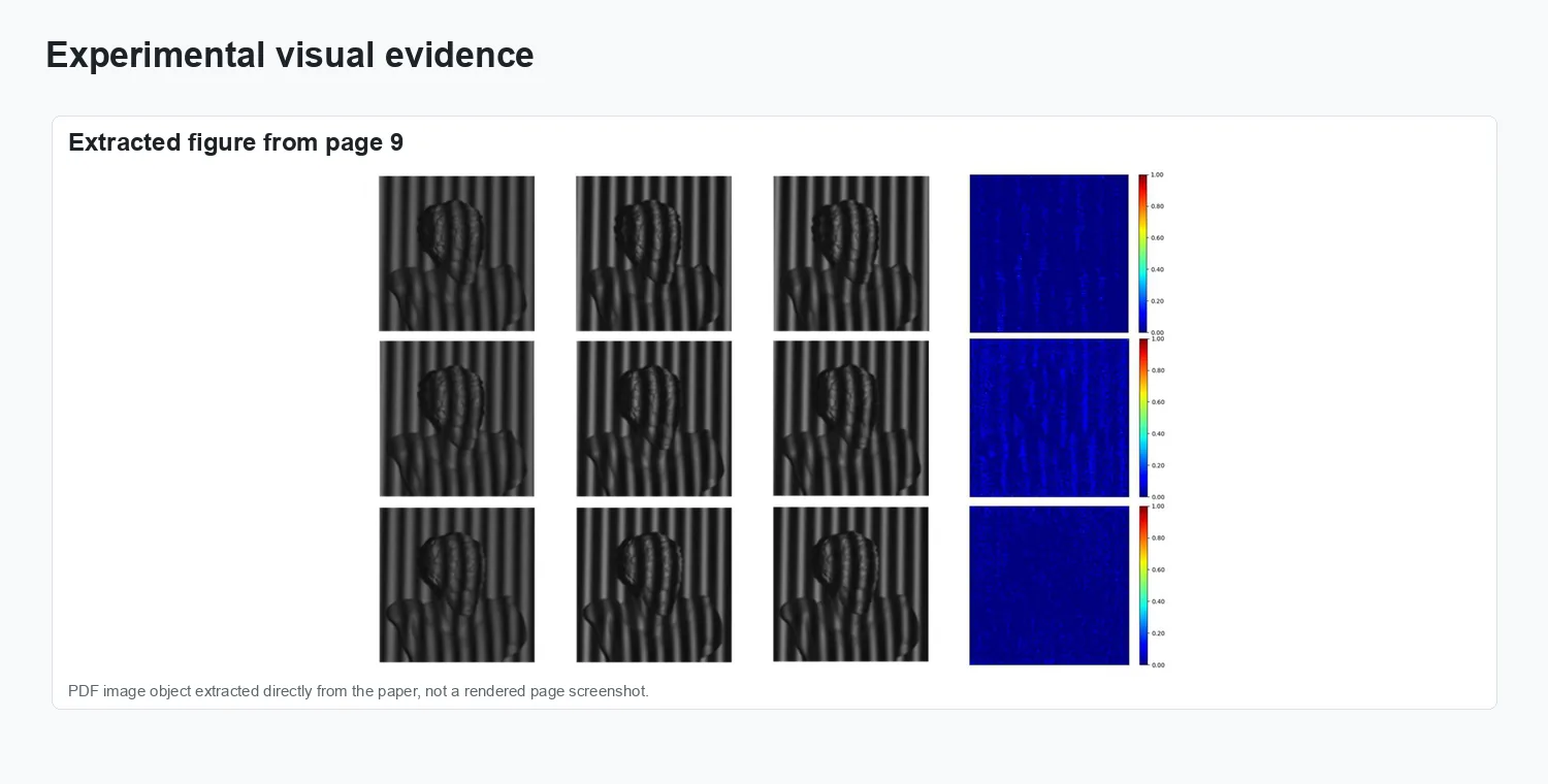
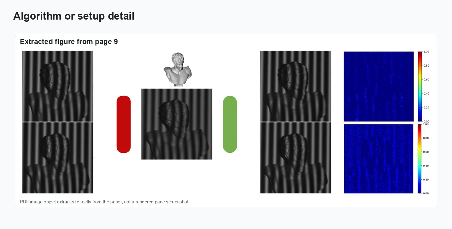
Experimental evidence.
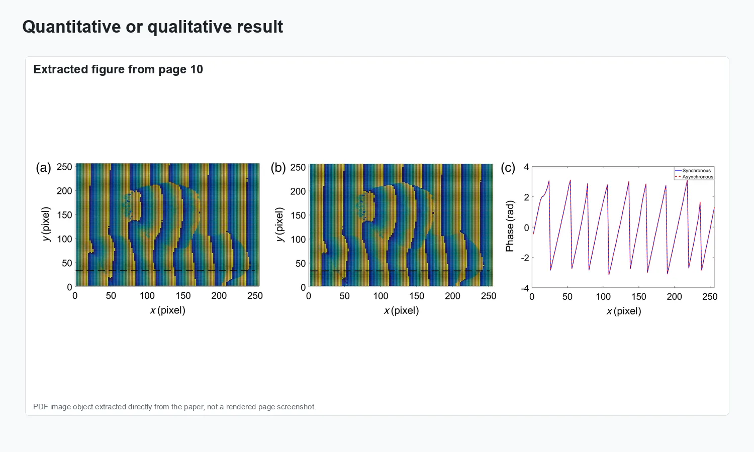
Result comparison.
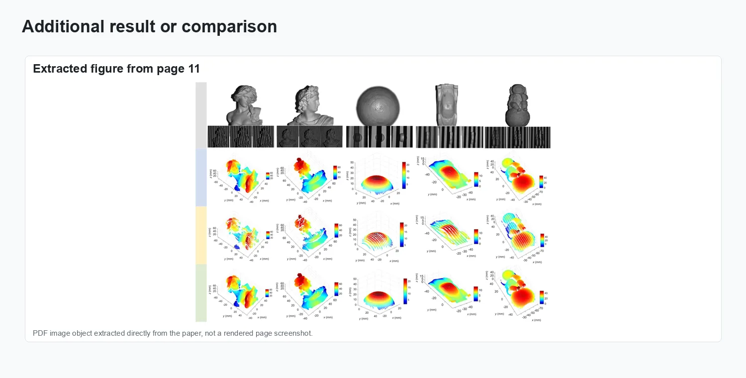
Additional visual result.
Results and impact
The evaluation reported in Advanced Photonics, 6(4):046004 is summarized through the figures above.