Kinematic target surface sensing based on improved deep optical flow tracking
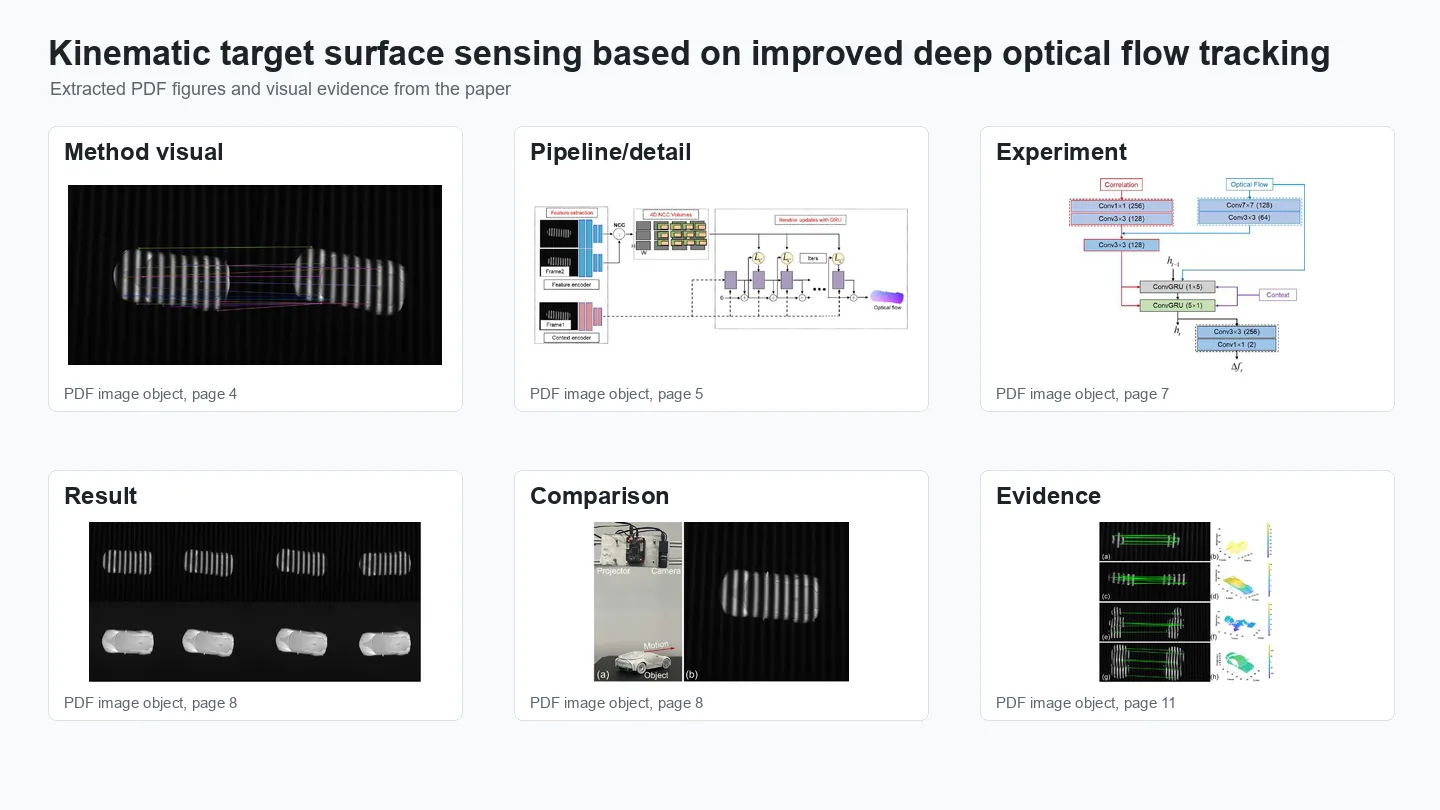
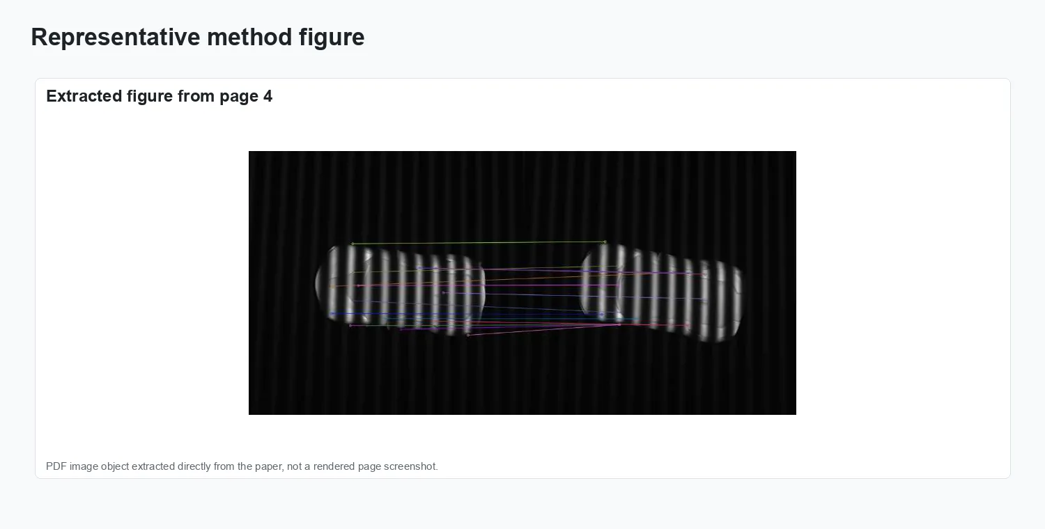
Measuring the surface geometry of mechanical components while they are in motion—gears rotating, pistons reciprocating—is a key challenge for predictive maintenance and precision assembly. Standard structured light methods require the surface to be stationary during multi-frame fringe projection; any motion introduces inconsistencies that corrupt phase retrieval and 3D reconstruction. This paper reframes the problem as a tracking task: rather than requiring a stationary surface, deep optical flow is used to track individual surface points across structured light frames, and the tracked correspondences are used to warp and register fringe observations to a common reference frame before reconstruction. The optical flow network is improved with kinematic priors—since the target’s motion mode is known (rotation axis, frequency), the flow field is constrained to be physically consistent, reducing drift and improving long-sequence tracking accuracy. The motion-compensated fringes are then processed by a standard phase unwrapping pipeline. Published in Optics Express (2023), the method recovers sub-millimetre surface detail from kinematic targets moving at operational speeds, enabling non-intrusive surface health monitoring without stopping or marking the target.
Problem setting
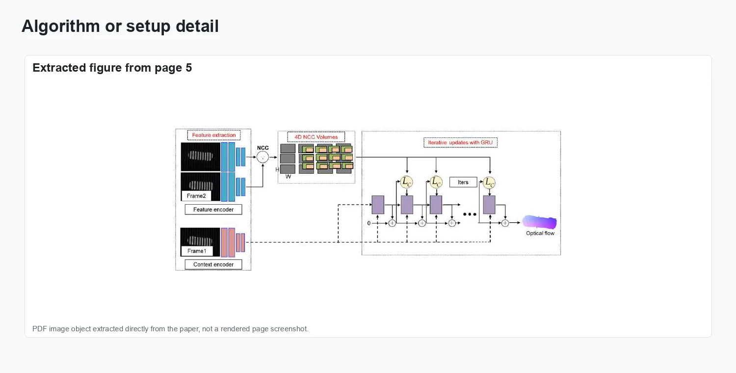
Sensing the surface geometry of kinematic targets—mechanical components undergoing known constrained motion—is critical for machine health monitoring and precision assembly but is complicated by target motion during structured light illumination. This work proposes to use improved deep optical flow tracking to estimate surface point trajectories across structured light frames, enabling accurate surface reconstruction from moving targets. The deep optical flow network is improved with domain-specific training data and a motion-consistency loss that exploits known kinematic constraints of the target.
The figures below collect representative visual evidence from Optics Express, 31(23):39007–39019.
Method and visual evidence
The figures below summarize the paper’s setup, signal flow, and visual evidence.
Method overview.
Representation and setup.
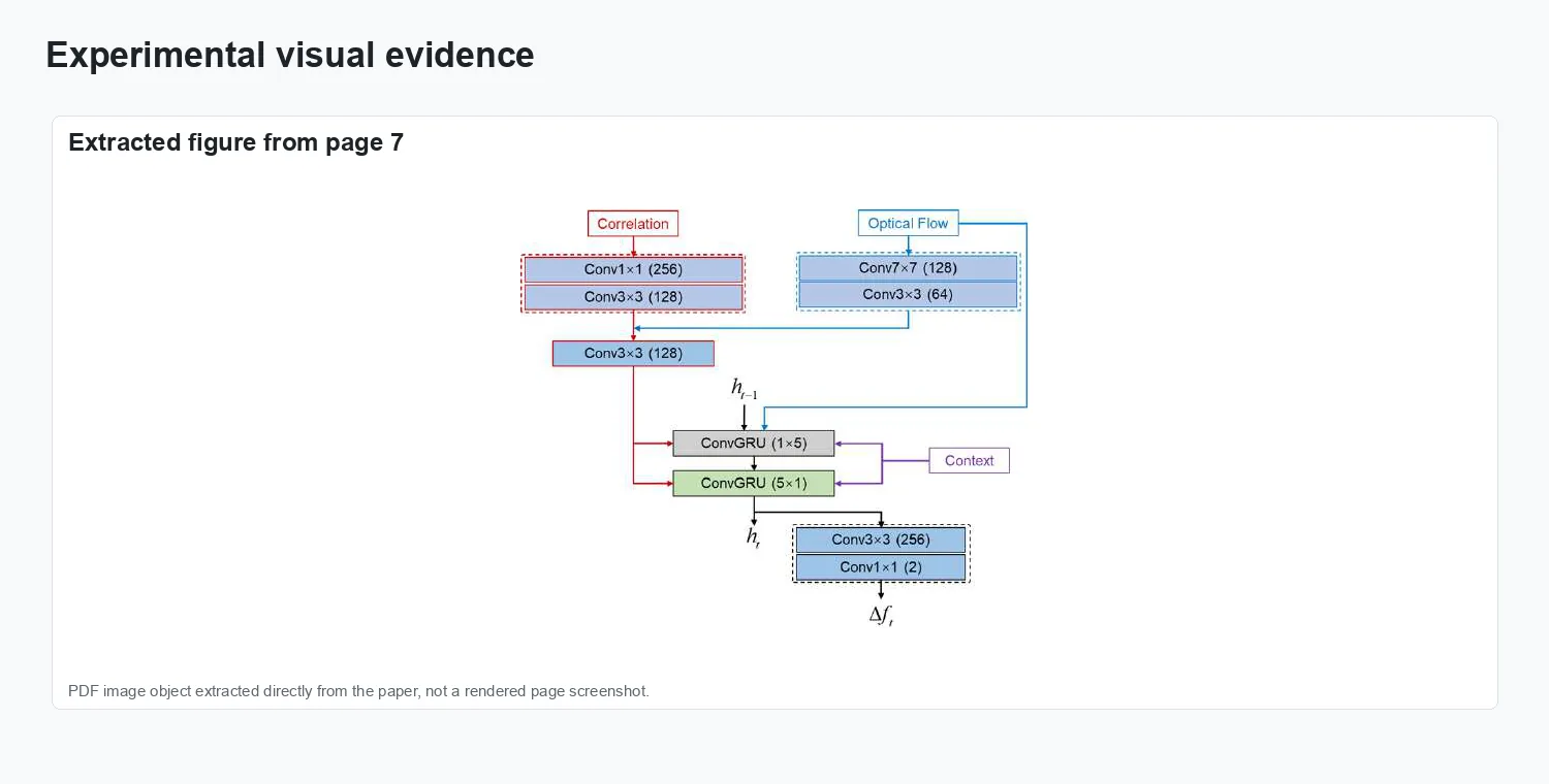
Experimental evidence.
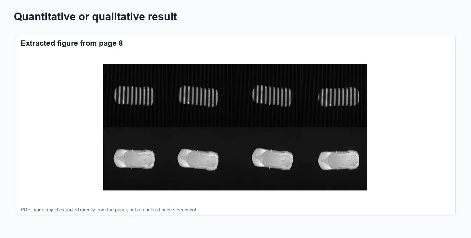
Result comparison.
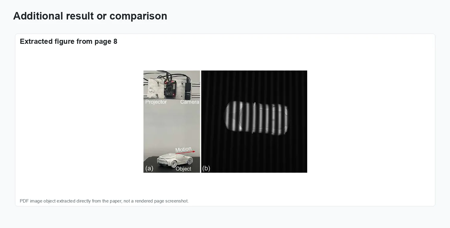
Additional visual result.
Results and impact
The evaluation reported in Optics Express, 31(23):39007–39019 is summarized through the figures above.